1.Stepper Motor
2.What
is a Stepping system?
3.DC Brush
Motor
4.Small
Brushless DC Motor
Stepper Motor
Motors convert electrical
energy into mechanical energy.A Stepper Motor converts
electrical pulses into specific rotational movements.The
movement created by each pulse is precise and repeatable,which
is why step- per motors are so effective for positioning
applications.
Permanent Magnet Stepper Motors incorporate
a permanent magnet rotor,coil windings and magnetically
conductive stators.Energizing a coil winding creates an electromagnetic
field with a north and south pole .The stator carries the magnetic
field.The magnetic field can be altered by sequentially energizing
or "stepping" the stator coils which generates rotary motion.
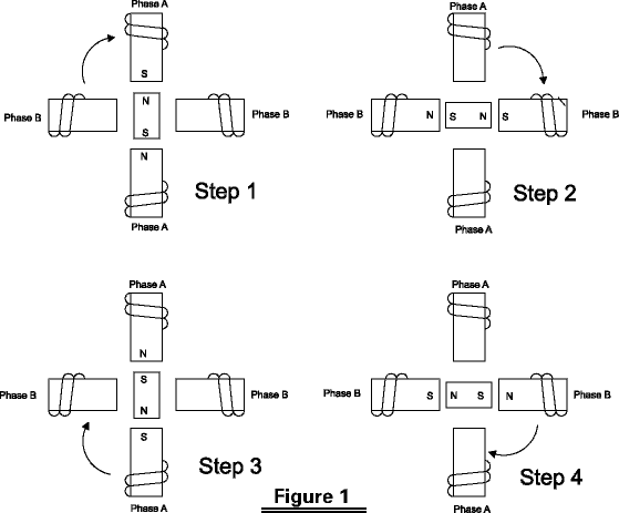
Figure 1 illustrates a typical
step sequence for a two phase motor.In Step 1 phase A of
a two phase stator is energized.This magnetically locks the rotor
in the position shown,since unlike poles attract,W hen phase A
is turned off and phase B is turned on,the rotor rotates 90°„ clockwise.In
step 3,phase B is turned on but with the polarty reversed from
Step 1,this causes another 90°„ rotation.In Step 4, phase A is turned off and
phase B is turned on,with polarity reversed from Step2.Repeating
this sequence causes the rotor to rotate clockwise in 90°„ steps.
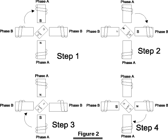
The stepping sequence illustrated
in figure 1 is called "one phase on" stepping.A more common method
of stepping is "two phase on" where both phases of the motor are
always energized.However,only the polarty of phase is switched
at a time,as shown in figure 2. With two phase on stepping the
rotor aligns itself between the "average" north and "average" south
magnetic poles.Since both phases are always on,this method gives
41.4% more torque than "one phase on" stepping.


Half Stepping
The motor can also be "half
stepped" by inserting an off state between transitioning
phases.This cuts a stepper's full step angle in half.For
example,a 90°„ Stepper Motor would move 45 on each half step,figure3.

However,half stepping typically results in a 15%-30% loss of torque depending on step rate when compared
to the two phase on stepping sequence.Since
one of the windings is not energized during
each alternating half step there is less electromagnetic force
exerted on the rotor resulting in a net loss of torque.
|
 |
DC Brush Motor
Principles of operation
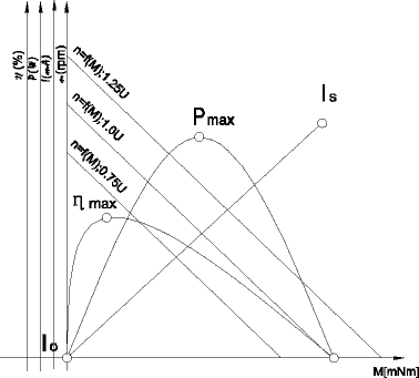
Reference to the chart reveals useful performance
information valid for all fulling servomotors.
It shows speed n, current I, output power P and efficiency ¶« plotted
against torque M for a given supply voltage U. Torque M is a function
of the current I and the torque constant k (expressed in Nm/A).
The motor develops its maximum torque Ms at stall (n=0), when the
current is maximum and determined only by the supply voltage U
and the rotor resistance R:
 With increasing
speed, an increasing back EMF E is induced in the armature which
tends to reduce the current: With increasing
speed, an increasing back EMF E is induced in the armature which
tends to reduce the current:

The value of E is the product of angular speed ¶ō (expressed in
rad/s) and the torque constant (expressed in V/rad/s=Vs=Nm/A):
E = k¶ō
Thus, the supply voltage splits into two parts: RI, necessary to
establish the current I in the armature, which generates the torque
M, and k¶ō to overcome the induced voltage, in order to generate
the speed¶ō:
U = RI + k¶ō
No-load speed no is a function of the supply voltage and is reached
when E becomes almost equal to U; no-load current Io is a function
of friction torque:

Power output P is the product of angular speed¶ō and torque M (P
= M.¶ō); for a given voltage it reaches its maximum Pmax at half
the stall torque Ms, where efficiency is close to 50%. The maximum
continuous output power is defined by an hyperbola delimiting the
continuous and intermittent operation ranges.
Efficiency¶«is the mechanical to electrical power ratio (¶«= Pm /
Pel). Maximum efficiency¶«max occurs at relatively high speed. Its
value depends upon the ratio of stall torque and friction torque
and thus is a function of the supply voltage:

The maximum continuous torque depends upon dissipated power (I2R),
its maximum value is determined by:

Where Tmax is the maximum tolerated armature temperature, Tamb
is the ambient temperature, Rmax is the rotor resistance at temperature
Tmax and Rth is the total thermal resistance (rotor-body-ambient).
At a given torque M, increasing or decreasing the supply voltage
will increase or decrease the speed. The speed-torque function
varies proportionally to the supply voltage U.

|
 |
Small Brushless DC Motor
Principles of operation
The differences between a DC motor having
a mechanical commutation system and a BLDC motor are mainly found
in :
- the product concept
- the commutation of phase currents.
From the user's point of view, brushless DC motors follow the same
equations as those with brushes: torque is proportional to current,
speed depends on the voltage and the load torque.
The commutation of brushless motors
In the conventional DC motor commutation takes place mechanically
through the commutator-and-brush system. In a BLDC motor, commutation
is done by electronic means. In that case the instantaneous rotor
position must be known in order to determine the phases to be energized.
The angular rotor position can be known by:
- using a position sensor (Hall sensor, optical encoder, resolver)
- electronically analyzing the back-EMF of a non-energised winding.
This is called sensorless commutation.
Use of Hall sensors
In general, BLDC motor have three phase windings. The easiest way
is to power two of them at a time, using Hall sensors to know the
rotor position. A simple logic allows for optimal energizing of
the phases as a function of rotor position, just like the commutator
and brushes are doing in the conventional DC motor.
Use of an encoder or resolver
The rotor position may also be known by use of an encoder or resolver.
Commutation may be done very simply, similar to the procedure with
Hall sensors, or it may be more complex by modulating sinusoidal
currents in the three phases. This is called vector control, and
its advantage is to provide a torque ripple of theoretically zero,
as well as a high resolution for precise positioning.
Use of Back-EMF analysis
A third option requiring no position sensor is the use of a particular
electronic circuit. The motor has only three hook-up wires, the
three phase windings are connected in either triangle or star.
In the latter case, resistors must be used to generate a zero reference
voltage. With this solution the motor includes no sensors or electronic
components and it is therefore highly insensitive to hostile environments.
For applications such as hand-held tools, where the cable is constantly
moved, the fact of just three wires is another advantage.
The functioning of a sensorless motor is easy to understand. In
all motors, the relation of back-EMF and torque versus rotor position
is the same. Zero crossing of the voltage induced in the non-energised
winding corresponds to the position of maximum torque generated
by the two energized phases. This point of zero crossing therefore
allows to determine the moment when the following commutation should
take place depending on motor speed. This time interval is in fact
equivalent to the time the motor takes to move from the position
of the preceding commutation to the back-EMF zero crossing position.
Electronic circuits designed for this commutation function allow
for easy operation of sensorless motors.
Small Brushless DC Motor
As the back-EMF information is necessary to know the rotor position,
sensorless commutation doesn't work with the motor at stall. The
only way of starting is to pilot it at low speed like a stepper
in open loop.
Remember:
- for commutation, position sensors are necessary when operating
in incremental mode
- sensorless commutation is recommended only for applications running
at constant speed and load.
Operating principle of BLDC motors:
It follows the same equations as the DC motor using mechanical
commutation except that parameters like iron losses and losses
in the drive circuit are no longer negligible in applications where
efficiency is of prime importance.
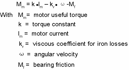
Iron losses
They depend on speed and, in the torque formula, may be introduced
as viscous friction. The equation for useful motor torque becomes:

Losses in the electronics
The current and votage required by the motor and the drive circuit
to operated at the desired speed and torque depend also on the
drive circuit.
As an example, a driver bridge in bipolar technique will reduce
the voltage available at the motor terminals by about 1.7V, and
the total current must include the consumption of the circuitry. |
What is a Stepping system?
Stepping systems have been used in industrial automation
for many years to accurately position machine tools, x-y
tables, feeders, etc. Unlike typical AC variable speed
drives (used for velocity control), a stepping drive and
Stepper Motor is used primarily for position control. A
typical single axis Stepping system consists of a Stepper Motor controller/ indexer, a motor drive, a motor (with
or without gearbox), and a power supply. A stepper is typically
commanded by two digital inputs: a digital pulse train
and a direction bit. A single pulse on the pulse input
moves the motor one step increment in the direction (CW
or CCW) set by the direction bit.
- Controller/ Indexer
The controller/ indexer is responsible for outputting
the pulse and direction commands to the drive. PLCs
distributed by China Stepper Motor Inc., as well
as many other 3rd party products, can be used to control
the SureStep line. The frequency of the pulse
train controls the velocity of the motor, where the
number of pulses determines the length of the move.
The direction signal determines in which direction
the motor will rotate.
- Stepper Power Supply
The power supply plays a dual role: it supplies the main
power to the motors as well as the power to optically-isolated
digital inputs. The motor power is typically provided
by a linear non-regulated power supply. The SureStep
power supply has a 32 VDC @ 4A (when fully loaded,
41 VDC unloaded) output to supply power to the motor
via the drive. Also, the digital interface between
the drive and the controller/ indexer should be powered
by the isolated +5 VDC (500 mA max) regulated output.
The motor power and the digital interface power are
typically isolated since the motor power source is
extremely "noisy" when loaded. Using the motor power
for the interface might lead to false pulse commands
thereby creating undesired system movement. One SureStep
power supply can provide both motor power and interface
power to a least 2 complete SureStep drive/
motor combinations.
- Stepper Drive
The drive translates the pulse and direction commands
from the controller/indexer and converts them into
actual motor movement. For each pulse from the controller,
the drive will move the motor "one step" in the direction
indicated by the direction command. The SureStep
microstepping drive provides 4 different step resolutions
for use in a wide range of applications. They range
from 1/2 stepping (400 steps/rev) to 1/50 stepping
(10,000 steps/rev) when used with a 1.8°„ (200 full
steps / rev motor). The SureStep drive can be
configured for use with all SureStep brand motors,
as well as many other 3rd party 2-phase, bipolar Stepper Motors that require 0.4 to 3.5 Amps/phase to drive
them. The drive also features a "test mode" that allow
the drive and motor system to be tested without being
connected to a controller/indexer. This feature enables
an on-board indexer that moves the motor 1/2 revolution
back and forth in half-step mode so the user can easily "move" the
system while troubleshooting. An idle current cutback
feature can be used to conserve power and reduce heat
by cutting the power to the motor by 50% if no step
pulses are received for 1 second. All the SureStep
drive settings are done through a 9-position dip switch,
which means that NO SOFTWARE or external resistors
are required to configure the drive.
- Stepper Motor
The motor converts the power from the drive into rotational
movement. Unlike AC motors, Stepper Motors have 100%
current (idle-current cutback disabled) applied to
them all the time regardless of load on the motor.
The motor is moved in "steps" (one per command pulse)
and will hold at its present position if no command
pulses are received. The SureStep line of motors
are built to provide high-torque for their frame size
which ranges from NEMA 17 to 34. All SureStep
motors have only 4 leads and are connectorized, which
greatly reduces the chance of mistakes while wiring
the motor to the drive. Many other motor brands typically
have 6 or 8 leads, which can cause confusion while
wiring the system.
NOTE: For further details or technical specifications,
select the desired product category and select the "Products" tab
and click on the desired "Item Code" link, or select
the "Technical Info" tab.
|

